
Utilising CFD Analysis For Perfect Tank Mixing
Transvac Tank Jet Mixers have been successfully adopted for in-tank mixing throughout the Oil & Gas, Pharmaceutical, Chemical, Food and Waste Water industries. Tank Jet Mixers use 1-part motive fluid to entrain 3-parts suction fluid, meaning low motive flow requirements and pump duties are required to achieve quick mixing times.
By installing a simple recirculation line with a pump externally, the mixers can offer an in-tank mixing arrangement with no moving parts inside the tank. Once installed, the Jet Mixers are virtually maintenance free.
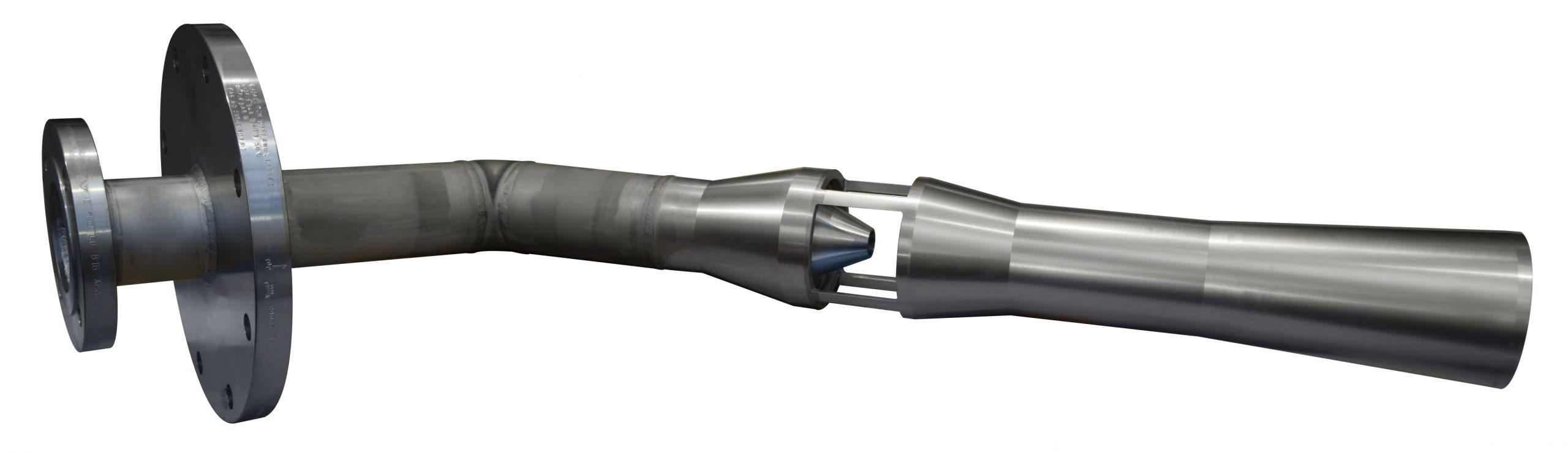
Each Jet Mixer is custom designed. Transvac will specify the required motive flow and pressure to achieve the required tank turnover and/or mixing time based on each individual client’s requirements. Otherwise, if there is an existing pump on site, the mixer can be designed to suit the available duty.
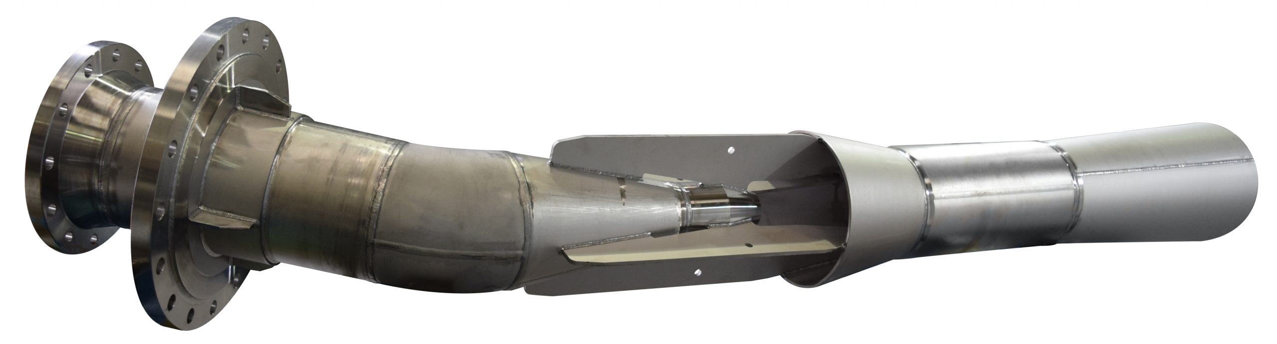
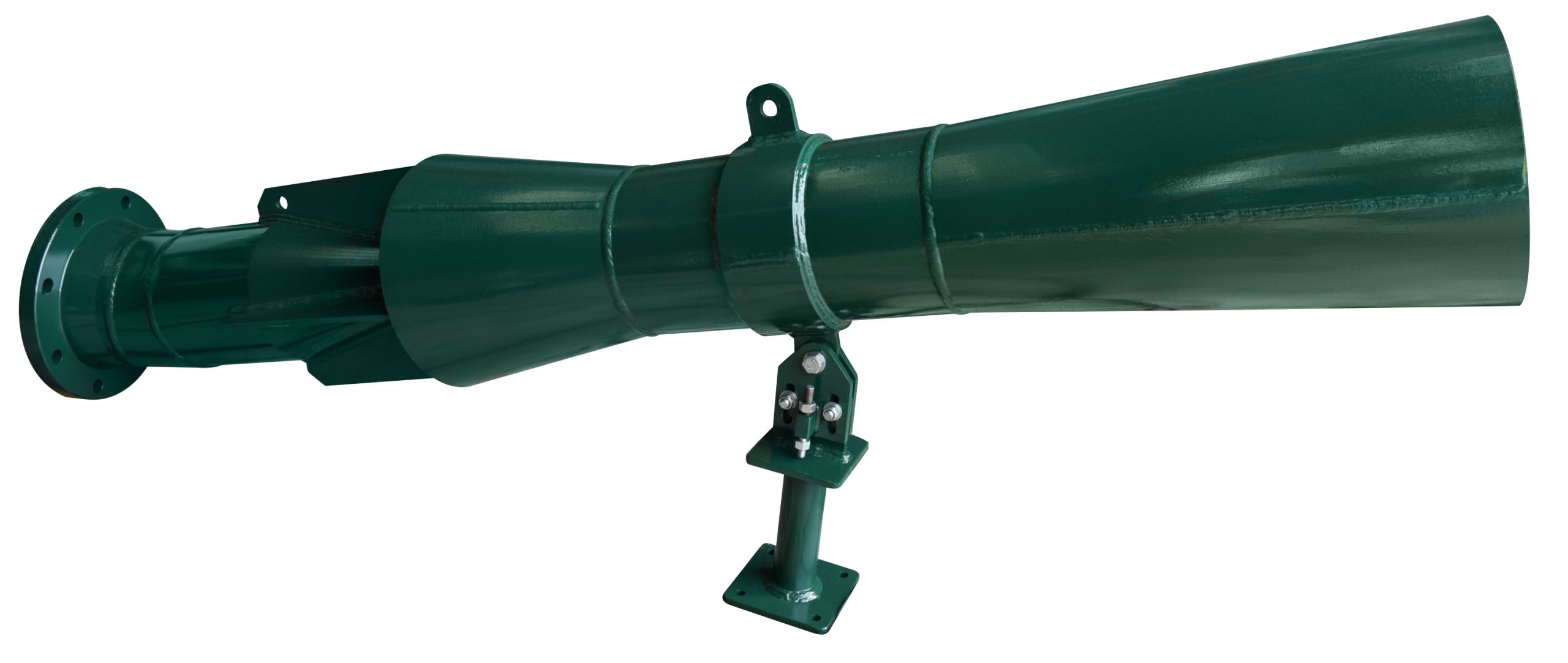
Depending on the tank accessibility, mixers can be designed for installation in-tank, on a manifold, through-the-wall or on a dip leg. Transvac supply the majority of mixers with an angle-creating spool piece, designed to direct the flow in the tank. The spool angle may be dependent on the tank geometry and mixing requirements. For larger tanks, multiple mixers on a manifold are often required to ensure the full contents are engaged by the mixers.
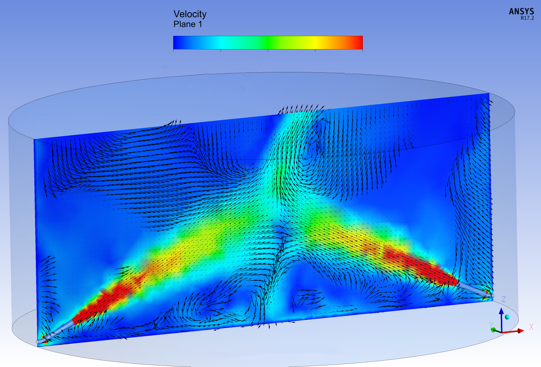
Where the mixing quality throughout the tank is critical to the process, such as achieving a certain pH level, homogeneity or temperature, Transvac engineers are able to offer detailed CFD analysis to optimise the arrangement of the mixers further.
In order to avoid bypassing of the fluid or dead-spots within the tanks, Transvac’s in-house CFD team can assess the quality of mixing based on various installation options, including manifold layouts, mixer inlet elevations and spool piece angles. This is particularly beneficial for larger tanks where dead-spots can be difficult to predict.
Transvac recently worked with two very different clients to offer CFD analysis alongside their tank jet mixer projects. One project was to determine the required spool angles for 8 mixers turning over waste water containing some solids. The second project utilised CFD to determine the best design for multiple mixers across 6 diesel tanks, each containing 2 identical Tank Jet Mixers.
Case Study Project 1:
Transvac supplied 8 (EIGHT) Tank Jet Mixers and manifold design for the following service;
Fluid : Waste Water containing small solids
Tank Geometry : 20.3 m ID x 21.7 m
Working Volume : 6,182 m3
Mixer Motive : 23.75 m3/hr and 3.5 bar (g) per mixer
Mixer Discharge : 95 m3/hr per mixer
Mixing Time : 2.5 hours
Case Study Project 2:
Transvac supplied 2 (TWO) identical Tank Jet Mixers and supports to installed per tank for the following service;
Fluid : Diesel
Tank Geometry : 28 m ID x 12 m
Working Volume : 10,000 m3
Mixer Motive : 280 m3/hr and 6 kg/cm2g per mixer
Mixer Discharge : 1,120 m3/hr per mixer
Mixing Time : 1 hour 20 minutes
Summary:
To summarise Transvac’s Tank Jet Mixer capabilities: In-house process design, mechanical design and manufacture of Jet Mixers;
- In-house CFD analysis to determine the optimum mixing arrangement
- Various material options including plastics, metals and exotics
- Manifold design and supply
- Support design and supply
If you would like to find out more about our CFD capabilities, please click here or contact us.