Transvac’s has the capability to carry out computational fluid dynamics (CFD) simulations on a range of different fluid-flow and industrial problems related to Ejector technologies. Transvac can offer customers CFD studies to demonstrate the performance of Ejector technology for their specific applications.
CFD modelling is the starting point for many of Transvac’s development projects. The use of computational modelling can reduce development time and reduce costs when a project reaches the prototyping phase of development.
Process conditions such as pressures; flows; material properties; and physical boundaries, taken from the real-world or design conditions, are inputted to determine a baseline of system performance. This information then forms the basis of physical test of performance in Transvac’s Ejector test facility.
Physical testing data is used to validate the initial CFD figures and drive the project forward. This data can either be provided by experimental testing in Transvac’s R&D facility or by data found in literature.
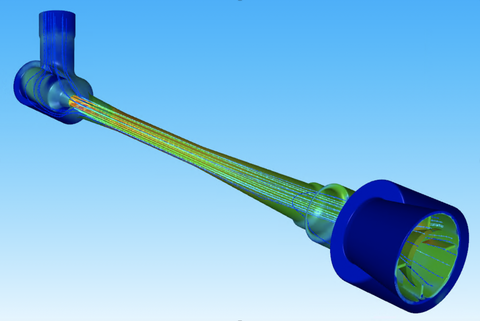
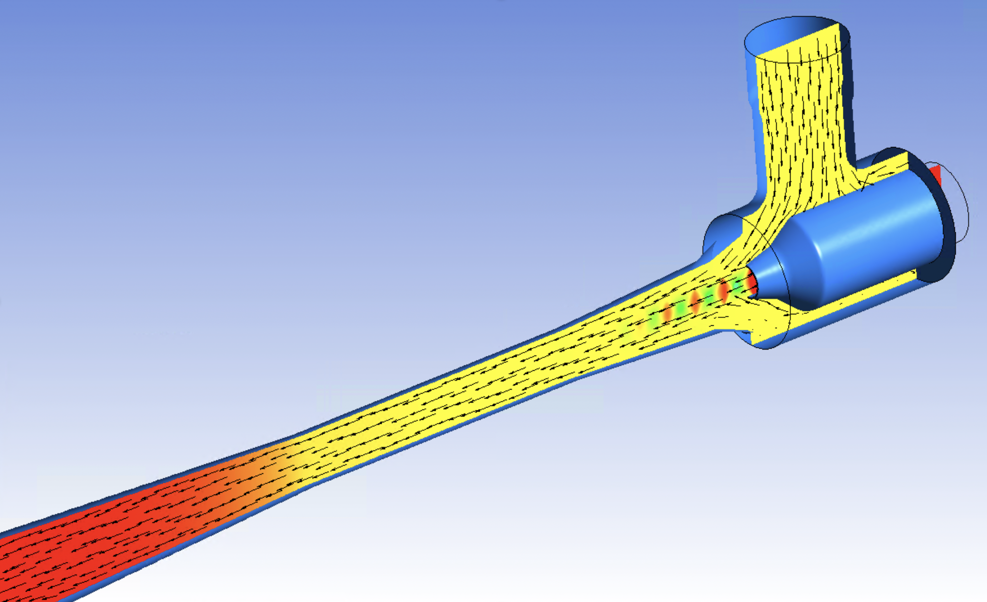
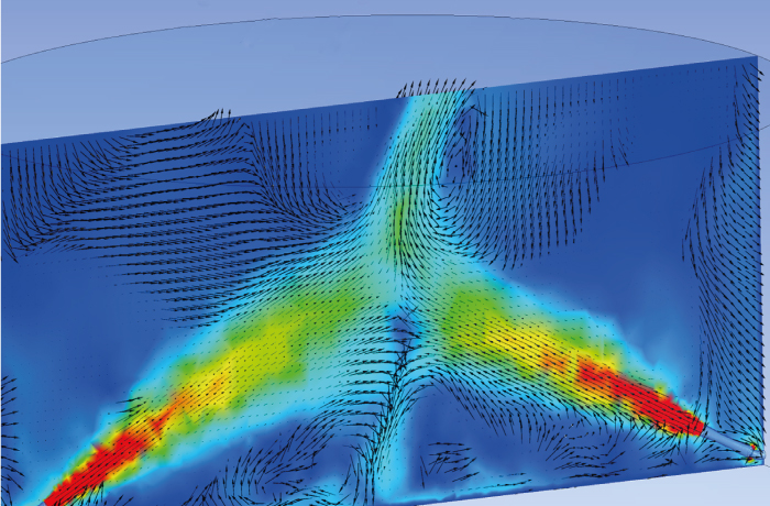
Computational Fluid Dynamics (CFD) is a division of fluid mechanics used to solve problems involving fluid flows using computer simulation to solve the Reynolds Averaged Navier-Stokes (RANS) fluid flow equations. It allows the engineers to ‘see into the flow’ within ejectors; pipes; and mixing tanks and probe the physical conditions calculated by the selected CFD models.
CFD is a mature simulation technology and is now a part of many modern engineering projects. Transvac’s studies often preface the physical manufacture of their novel fluid handling technologies.
Transvac’s core CFD competencies are:
Transvac’s CFD team has extensive experience in other areas of fluid flow modelling.
When real-world or scale testing is not viable a CFD study can provide a baseline of feasible performance figures. For example, Gas-Gas Ejectors and Tank Jet Mixing applications where the equipment scale and availability of fluids is an issue. A CFD study can also be used to for a FAT (Factory Acceptance Test) where it physically impossible to physically test the supplied Ejector.
Transvac not only performs CFD projects for customer specific Ejector applications. Transvac maintains continuous Ejector technology development, using a mixture of CFD; physical testing; and modelling research. CFD is often used as an initial step into what could be long and costly physical development programmes.
Transvac are continuously refining their designs for their Liquid Jet Compressors Ejectors (LJC); Multi-phase Ejectors; and Tank Jet Mixing range. The goal of this work is a combination of maximizing efficiency and improving fluid handling performance. This work is a combination of optimisation of existing designs and radical experimental designs.
Following these CFD programmes with physical testing with a better understanding of the flow behaviour and hence a great certainty of success in the development.
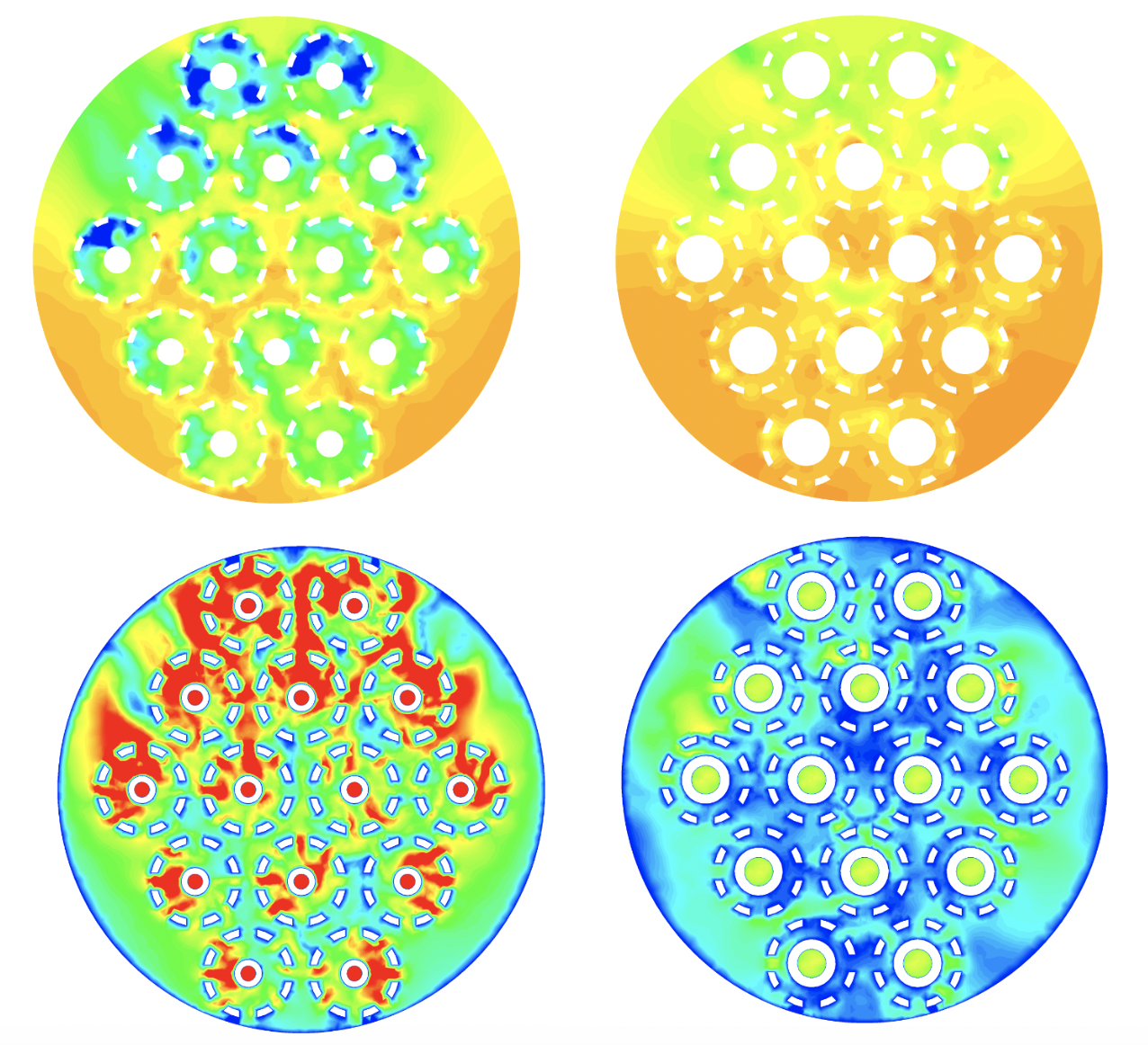
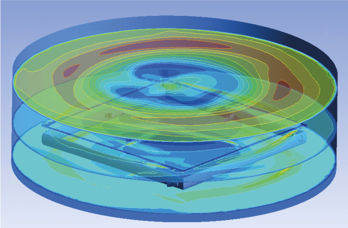
CFD modelling is perfectly suited to studies concerning Tank Mixing Solutions. Transvac can offer a detailed CFD analysis to optimise the arrangement of Jet Mixers in tanks to avoid fluid bypassing or stagnation.
Transvac can assess the quality of mixing based on various installation options, including manifold layouts; Jet Mixer inlet elevations; and angles. This is particularly beneficial for larger tanks where stagnation can be difficult to predict without CFD. More complex studies can be undertaken focusing on the mixture’s physical properties as well as fluid concentrations.
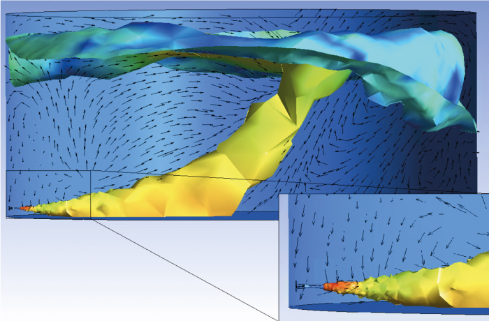
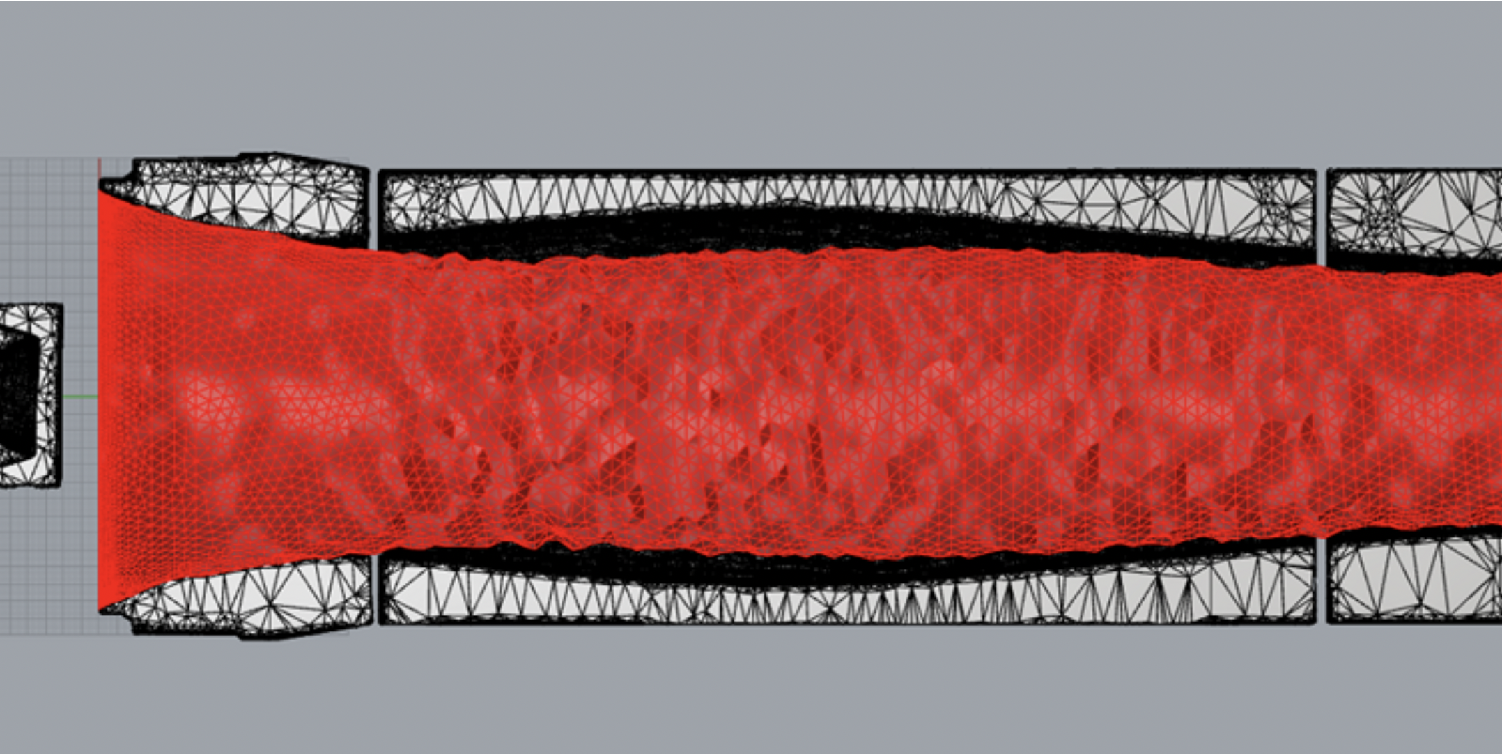
Transvac have performed significant CFD studies on Slurry and Sand Pumping applications with the objective of improving Ejector resistance to adverse media and conditions. From these studies Transvac have developed their own code that allows the modelling of erosion due to impingement and cavitation. These programmes have been validated by measurements performed on client’s sites.
These product development programmes have enabled Transvac to offer abrasion resistant Ejectors fitted with high wear components that are highly resistant to particle impingement and cavitation. The application of CFD allows the targeting of wear components to areas of high erosion and hence reduce manufacture costs for the customer.
Although the majority of our work is self-funded. We have worked as the senior research partner on several occasions with the University of Nottingham’s faculty of Chemical & Environmental Engineering. These studies have offered a handful of University research students to experience real-world CFD modelling projects.
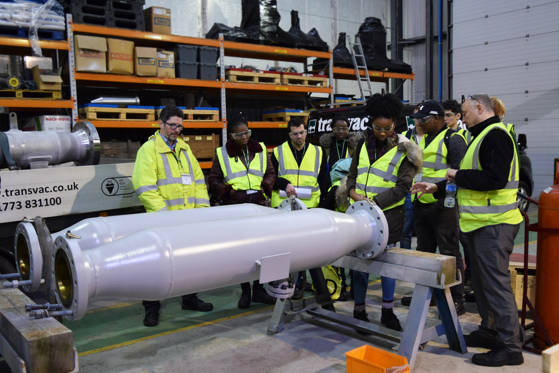
Transvac also supports University students through a long-established Internship Programme, and offers regular department visits to tour Transvac’s facilities.