Every Ejector installation requires some level of control. This may be as straight forward as turning the Ejector on or off. There are a wide range of control strategies that can be employed to control the performance of an Ejector and how an Ejector interacts with your process. Below are some of the most common techniques;
Ejector performance can be controlled by throttling the high-pressure motive stream, which drives the Ejector. The most simple control, using this method, would be turning the Ejector on or off by turning on or off the motive stream.
The use of ‘motive throttling’ as a control technique cannot be applied equally to all Ejector types. There is a difference between liquid, gas and steam-driven Ejectors, and even different types of Gas Ejector as explained below.
Motive control is only effective when the Ejector operates in what we call “subsonic” mode. For an Ejector to be “subsonic”, the Ejector compression ratio (discharge press divided by suction press, where both are expressed in absolute pressure terms) must be less than approx 2. If the compression ratio is greater than 2 then the Ejector is termed “sonic” and motive throttling will not effectively control. Reducing the motive pressure to a sonic Ejector will result in it going “unstable” in operation, with motive fluid entering the suction system. This often happens unpredictably and very quickly.
For sonic installations, unless the Ejector Discharge pressure is reducing, we would typically recommend the recycle method.
The recommended method of controlling efficient Liquid-driven Ejectors (LJC/MJC’s) is to use the gas recycle method. However, less efficient Liquid-driven Ejectors (LJC’s) designs can be controlled by throttling the motive liquid stream using a valve or, if available a variable speed drive (VSD) pump. If a VSD is available, then a power / energy saving is possible, when the Ejector motive flow is reduced.”

Fig.1 Gas Ejector suction controlled by throttling HP Motive Gas
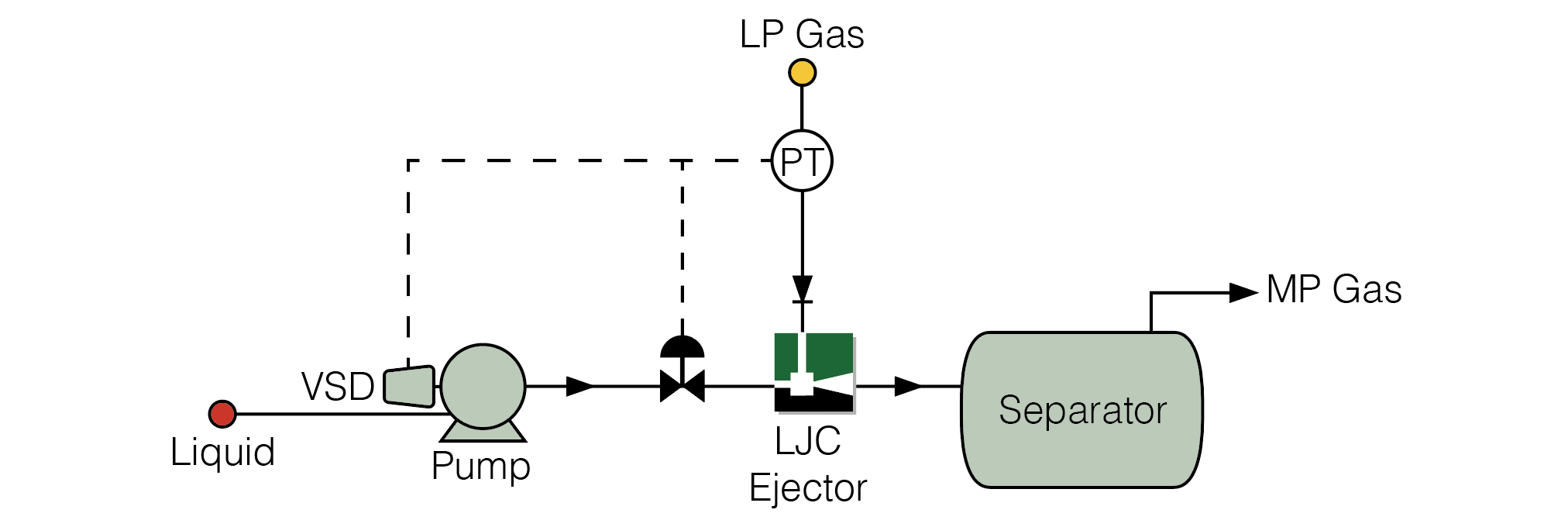
Fig.2 LJC Ejector suction controlled by throttling HP Motive Liquid with a valve or VSD Pump
The recycle method is one of the most common, robust control strategies we employ for our Ejector projects. It is primarily used for applications with varying suction flow-rate, or where a fixed pressure is required on the suction side of the Ejector. A good example of this is where an Ejector is used to vent or recover gas from tanks / vessels for applications such as Flare Gas Recovery.
When we design an Ejector, we must ensure it has the capacity to handle the maximum envisaged flow-rate from the tanks / vessels, i.e. its 100% duty point. However, commonly the gas flow-rate reduces far below the 100% duty point. With a reduced suction gas flow-rate and without control, an Ejector will continue to operate, but also reduce the pressure on upstream equipment, including tanks / vessels. This can be highly undesirable, especially if the mechanical design of tanks / vessels does not allow vacuum conditions. This is where the recycle control method offers complete protection.
The Recycle control method allows the Ejector to comfortably operate with its 100% suction gas flow-rate, even when the primary process does not provide the required gas. It is achieved by recycling gas from downstream of the Ejector, back into the suction side of the Ejector.
The amount of recycle is controlled by a valve and pressure instrument which monitors the suction pressure to the Ejector. If the pressure reduces, the valve opens to recycle ‘make-up’ gas back to the Ejector. When pressure regains, the valve closes again. With the correct instrumentation and valve selection, this method provides a highly accurate control. It has been used on numerous projects where pressure tolerance within tanks / vessels has been very low.
Liquid Jet Compressors (LJC’s) have a gas and liquid stream at the Ejector discharge, so gas must be recycled from a suitable point downstream, such as a separator.
If your process operates with large amounts of recycle over long periods of time, i.e. with reduced demand on the Ejector, it may be more efficient to consider using Multiple Ejectors as shown below.
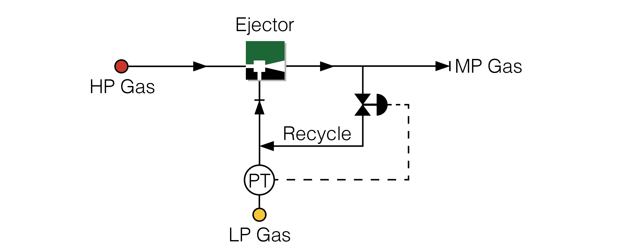
Fig.3 Gas Ejector using Recycle Control method
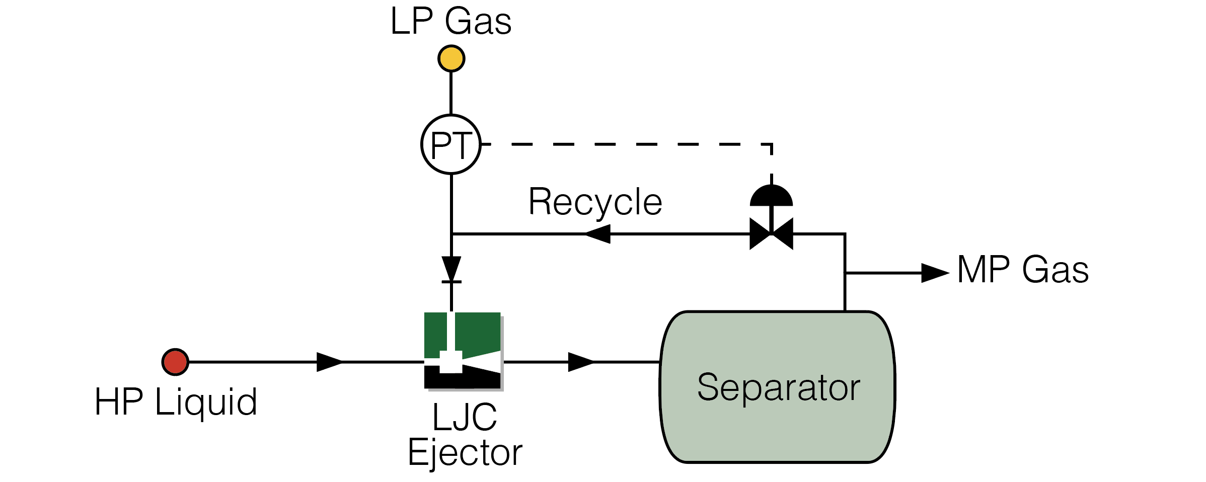
Fig.4 LJC Ejector using Recycle Control method
Note: Gas must be recycled from separator / downstream separation
When considering Ejector control methods, there are a number of opportunities to save energy (and therefore OPEX). One such example is the use of multiple Ejectors.
Simply put, instead of using one Ejector, the duty is split across two or more Ejectors. This approach provides flexibility to turn Ejectors on or off, as the process demands. So if demand is low, you only need to operate one smaller Ejector, instead of one large Ejector. This greatly reduces motive flow requirements and saves energy.
The duty can be split 50% / 50% across two identical Ejectors. This allows the Ejector system three modes of operation, 0% with Ejectors off, 50% with one Ejector in operation, or 100%, with both Ejectors in operation.
A more useful and common approach, however, is a 30% / 70% split. This allows four modes of operation. 0%, 30% with one (smaller) Ejector, 70% with one (larger) Ejector, or 100% with both Ejectors in operation.
Some projects do not allow any modifications once installed, such as Nuclear or Subsea Processing. Another approach is to install two or more Ejectors in parallel. Simple valving can change process streams from one Ejector to another (with a different design point), or operate both / additional Ejectors.
Although this approach requires multiple Ejectors and more control valves etc, it allows hands-free operating mode changes and a far more efficient use of the Ejector Motive stream.
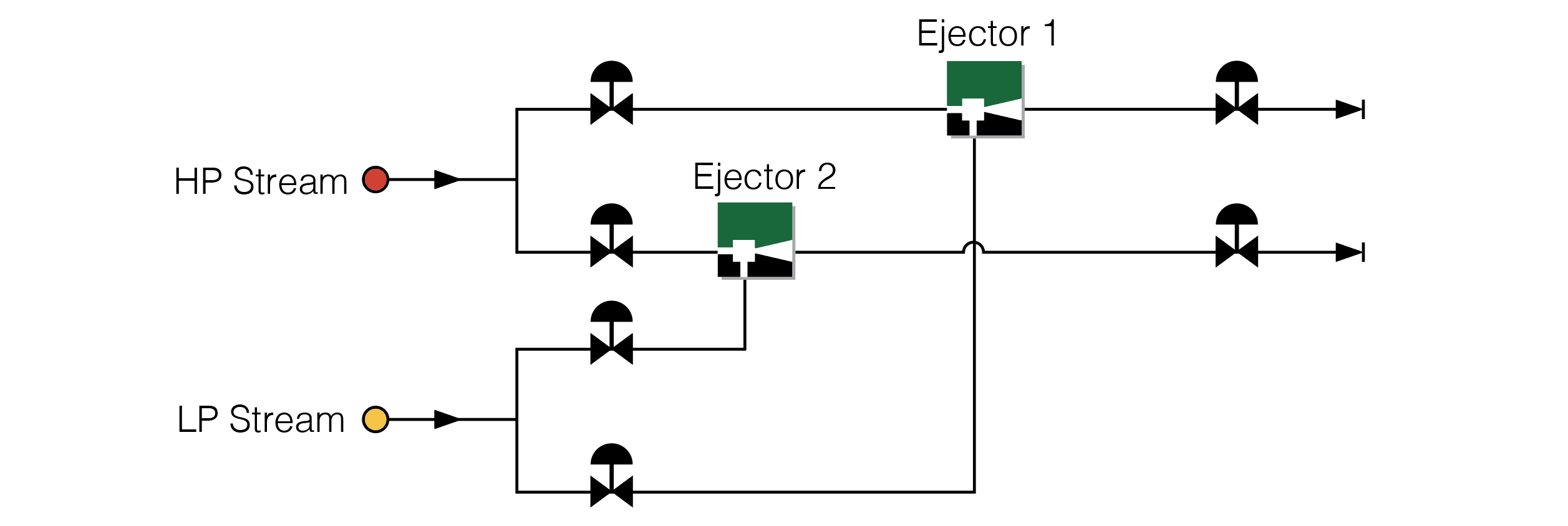
Fig. 5 Using two or more Ejectors in parallel provides flexibility and an opportunity to save energy. If process demand reduces, a single Ejector can be operated, greatly reducing motive flow requirements.
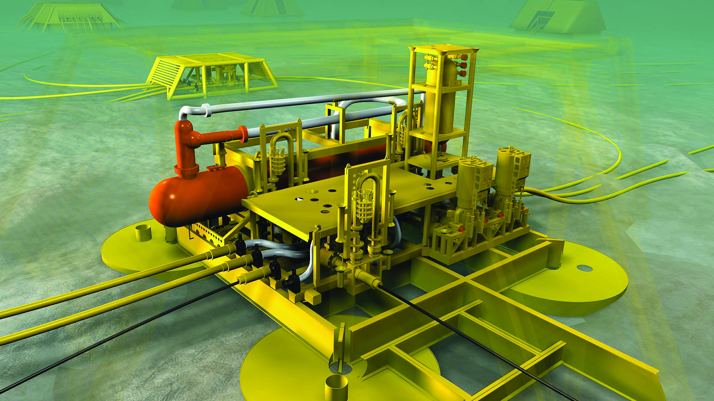
Using multiple Ejectors is an ideal strategy subsea processing facilities where change-out of equipment is not possible.
In some instances, changes to process may occur over a longer period of time, maybe many months or years (for example, declining / maturing oil and gas wells). Process conditions can also become far removed from the original design point.
It can be inefficient (or sometimes impossible) to use a single Ejector design to cover a very wide operating range. The good news is that Transvac has a unique solution to this challenge!
Transvac offers a patented, Universal Design Ejector which allows the internal nozzle and diffuser of the Ejector to be changed-out. Each set of ‘internals’ provides a new, efficient operating design point to suit the new process conditions. It’s like having a new Ejector!
The change-out of Universal Design Internals is usually scheduled during plant shut-down or maintenance periods. It is a quick and easy procedure, typically completed in a single shift, but can take as little as an hour.
Further information on our Universal Design can be found here.
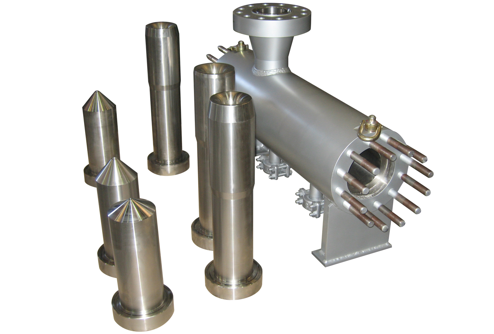
A Transvac Universal Design Gas Ejector, complete with replacement internals