Transvac Steam Jet Thermocompressors are energy saving devices that compress low pressure steam, often waste steam, to a higher useable pressure.
In this environmentally conscious world, companies within the Process Industries Sector are becoming more aware of the additional cost savings that can be made at the same time as committing to a friendly environment.
One such common area is the steam raising plant and the proportion of waste product that is put to atmosphere. If the amount of waste can be reduced and thereby have an effect on the amount that is being generated in the first place, then the environment will be improved and the running costs reduced. It is in this area of operation that the application of an SJT Steam Jet Thermocompressor can be advantageous.
Transvac has been designing innovative solutions for steam plant engineering and cost effective manufacturing for over 45 years. The Steam Jet Thermocompressor is a prime example of this commitment; the SJT is an energy saving device that compresses low pressure steam, often waste steam, to a higher useable pressure. All of Transvac’s Thermocompressors are designed and built to the customers specific criteria, for their intended application, to provide optimum performance and return on investment.
Paper and Board Industries
Desalination
Chemical, Petro-chemical, Oil and Power Generation
Rubber Industry
Food, Dairy, Pharmaceutical & Chemical Industries
Brewing Industry
Most Process Industries
Food Industry
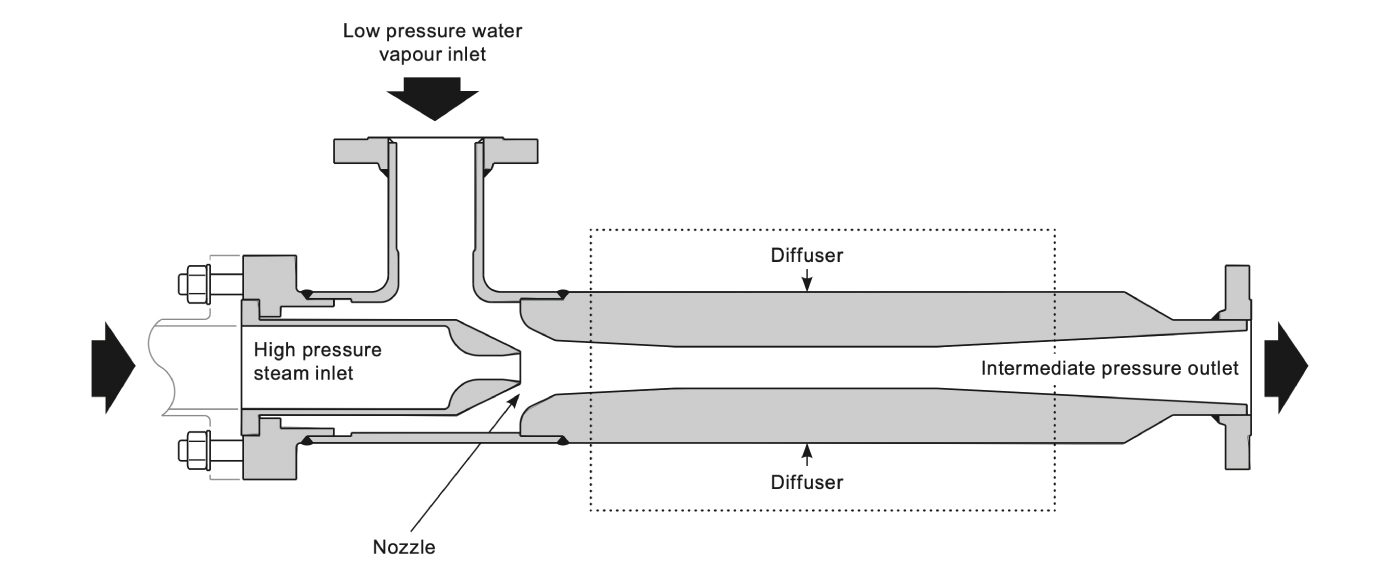
An SJT Steam Jet Thermocompressor can be described as a type of Ejector. It uses a jet of high pressure steam (called the Motive pressure) to entrain low pressure water vapour (called the Suction pressure). The two medium’s are intimately mixed and subsequently discharged at a pressure that lies somewhere between the motive and suction pressures.
High pressure motive steam enters the Thermocompressor and passes through the nozzle where the high pressure steam energy is converted into kinetic energy. On leaving the nozzle at high velocity, the steam enters the suction chamber where it is brought in contact with the suction stream. There is then an exchange of momentum between the motive and suction streams, resulting in an acceleration of the suction vapours, giving rise to their subsequent entrainment.
A uniform mixture results at the narrowest part of the diffuser (called the throat) and finally the reconversion of the velocity energy into pressure energy occurs in the diverging section of the diffuser. As a result, it then discharges at a pressure (Pd) that lies somewhere between the HP and LP pressures.
There are two types of Thermocompressor – sonic and subsonic. Although sonic and subsonic Thermocompressors may look similar, they behave differently and must be controlled differently. It is therefore important to consider this during the design phase of a project.
It is the compression ratio of a Thermocompressor determines whether is ‘subsonic’ or ‘sonic’. The compression ratio (K) is calculate by dividing the discharge pressure by the suction pressure of the Thermocompressor.
Subsonic and Sonic designs can be compared as follows;
Transvac offers several types of Thermocompressor. The first is the fixed nozzle type which cannot be controlled to any great extent, although some control is achievable by throttling the motive steam pressure via a separate valve upstream of the SJT Steam Jet Thermocompressor.
The other type relies on a motive steam regulating spindle to vary the cross sectional area of the motive steam nozzle. Unlike a throttling valve positioned upstream, the regulating spindle does not reduce the motive steam pressure, it simply varies the area through which the steam is flowing. This approach maximises the energy per kg of motive steam that is available at the nozzle to do the work. With an installation involving an upstream throttling valve, useful energy is lost in the throttling process.
SJT Steam Jet Thermocompressors utilizing a motive steam regulating spindle are often referred to as Variable Orifice Ejectors. The spindle is operated automatically. These should be specified in cases where the suction load, suction pressure or discharge pressure are continually varying, and it is necessary to control one or more of these process parameters as quickly as possible.
Note:
For cases which involve large variations in load, it is sometimes more cost effective to use several various sized units connected in parallel, than to have one large controlled unit. It may also be necessary to install a bypass valve in some applications.
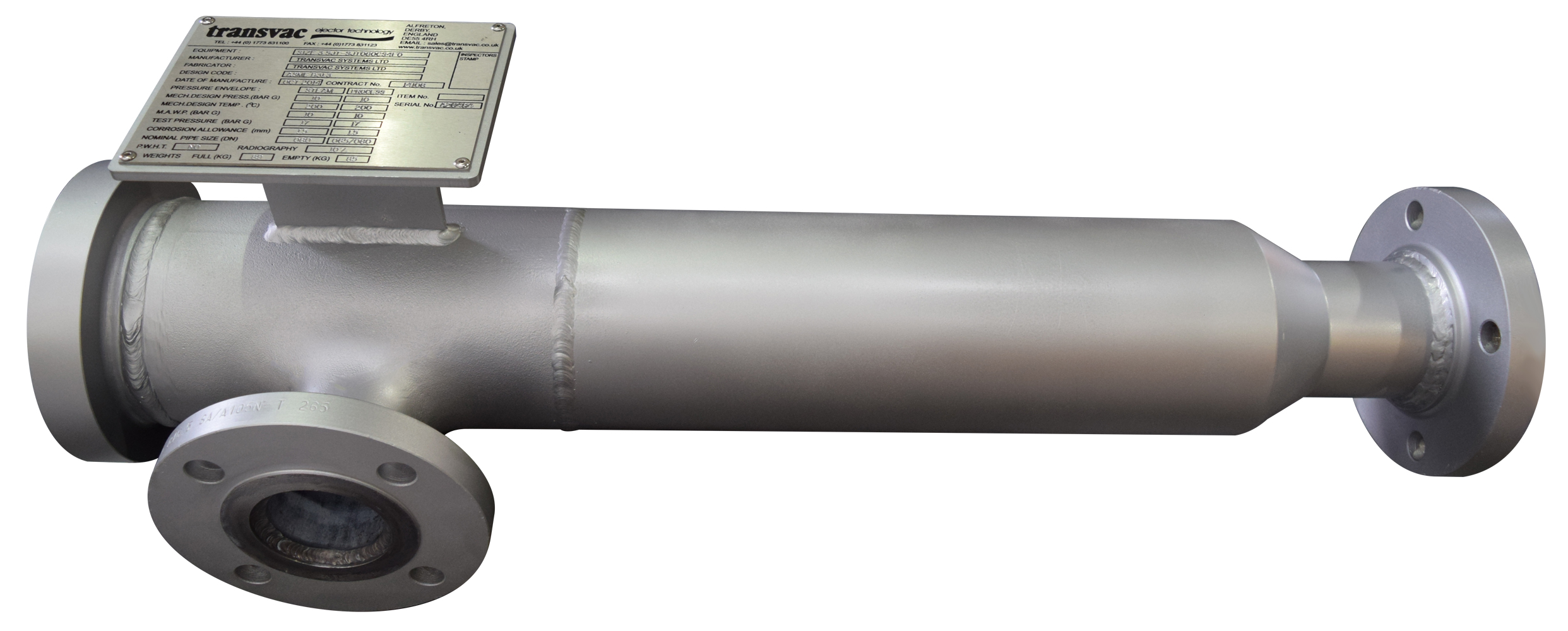
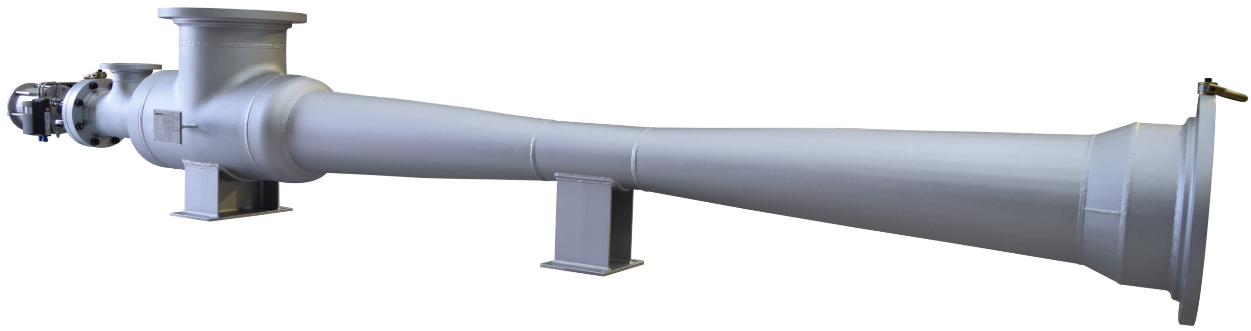
A ‘fixed’ type Thermocompressor
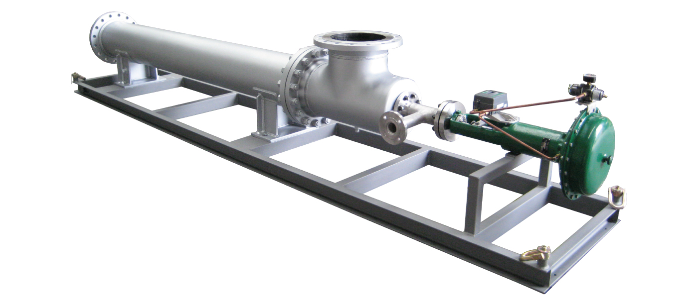
A ‘Variable Orifice’ type Thermocompressor complete with motive steam regulating valve
Thermocompressors have a robust, simple construction that consists of three fundamental components: Motive Steam Nozzle, Suction body and a Diffuser (Throat).
To offer complete flexibility, a wide range of materials of construction are available including stainless steels, carbon steel, Titanium, chrome molybdenum etc.
Further information about Materials of construction can be found here.